Views: 0 Author: Site Editor Publish Time: 2026-11-03 Origin: Site

High-value inventory loss and excessive energy consumption in commercial refrigeration often stem from a single design failure: the improper spatial configuration of evaporator equipment. Facility managers and contractors frequently invest in premium refrigeration hardware, only to experience hot spots, short-cycling, and rapid ice accumulation. These operational failures usually arise from a direct mismatch between equipment placement, racking layouts, and door locations. Airflow behaves predictably based on the physical constraints of the room. When evaporators are installed without considering storage geometry or access points, the entire refrigeration cycle degrades. This guide provides a technical evaluation framework for positioning evaporator units. We detail how to align airflow trajectories with storage geometry, insulation parameters, and access points. Proper alignment ensures thermodynamic stability, regulatory compliance, and maximum equipment lifespan.
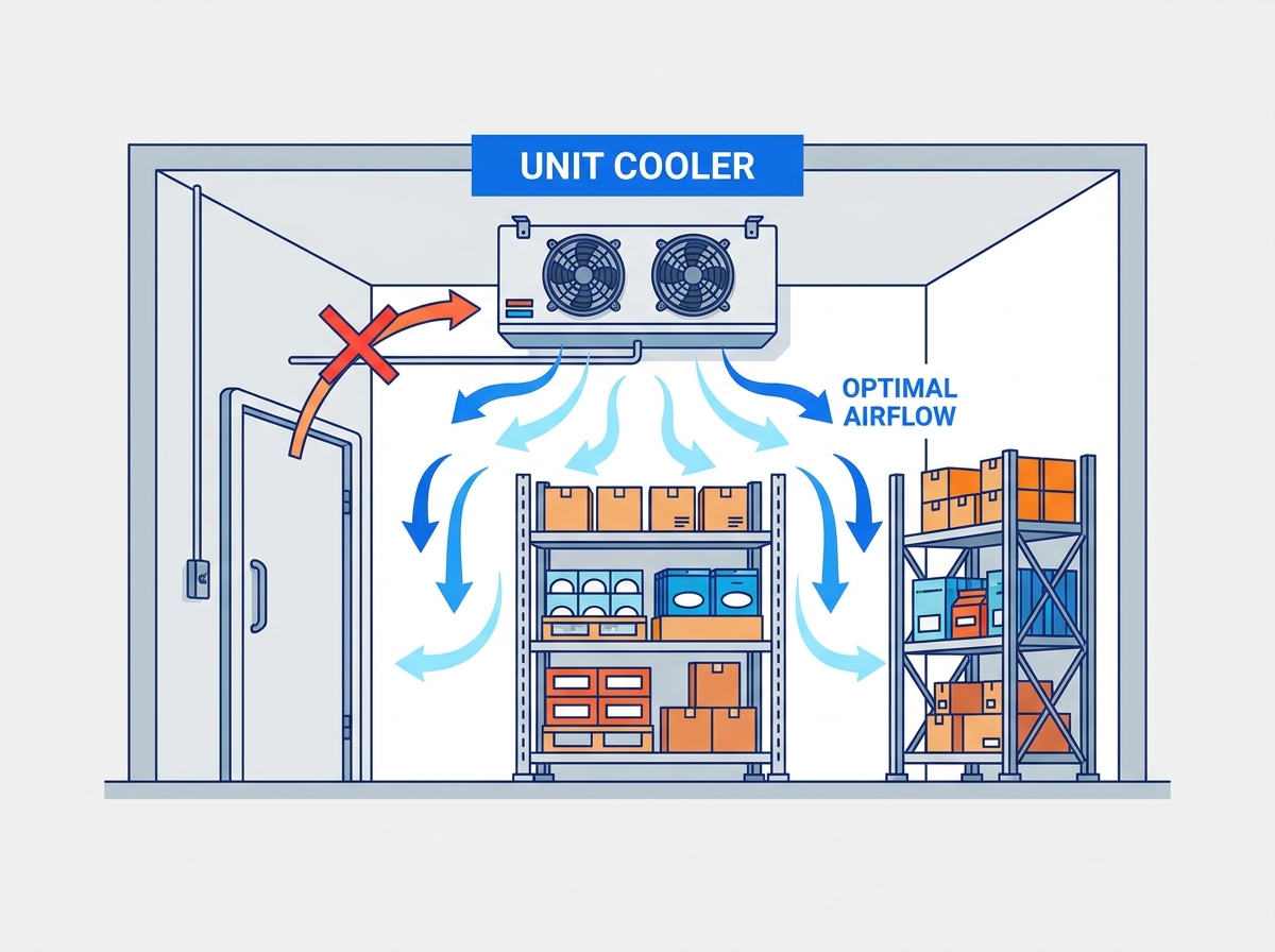
Airflow Dictates Layout: Racking orientation must be designed parallel to the discharge trajectory of cold room unit coolers to prevent static pressure buildup and dead zones.
Door Proximity is a Liability: Evaporators must never face access doors directly; doing so guarantees rapid moisture ingress, immediate coil freezing, and excessive energy draw during forced defrost cycles.
Profile Matching is Critical: Selecting specific equipment profiles—such as DD series unit coolers—depends entirely on ceiling height, aisle configuration, and required air throw distance.
Placement Drives Efficiency: Strategic positioning reduces operational expenses by minimizing compressor wear, lowering defrost frequency, and preventing product spoilage.
Designing effective cold room solutions requires strict adherence to thermodynamic principles. Cooling a space involves the continuous, volumetric removal of heat. This process relies entirely on unobstructed air circulation. If chilled air cannot reach the product, or if warm air cannot return to the coil, the system fails regardless of its rated capacity.
Uniform temperature distribution depends on throw distance and discharge velocity. Evaporator fans must generate enough velocity to push conditioned air to the furthest wall of the enclosure. This discharge trajectory must overcome the static pressure created by the room dimensions and stored inventory. If the throw distance falls short, the rear of the room remains unconditioned. This leads to rapid product degradation.
Pulling warm air across the finned evaporator coil is equally important. An unobstructed return air path maintains low-pressure system efficiency. Fans create a pressure differential. They push cold air out and pull warm air in. If stacked pallets or solid shelving block the return path, the fans choke. The system then recirculates the same localized air. The thermostat registers a false positive and shuts off the compressor prematurely.
The Coanda effect plays a significant role in refrigeration environments. When an evaporator discharges air close to a flat ceiling, the air plume clings to the ceiling surface. This physical phenomenon extends the horizontal reach of the chilled air. It travels further before dropping onto the product load. Installers must leverage this effect by mounting units at the correct distance from the ceiling panels. This ensures the air stream does not detach too early.
Return air temperature serves as the baseline metric for system health. The thermostat sensor must accurately reflect the ambient room condition. It should not just measure the localized air immediately surrounding the unit. Placing sensors in the direct path of the discharge air results in erratic cycling. The return air stream provides the most accurate average temperature of the entire cubic volume.
Thermal dead zones form wherever airflow is obstructed. Hot spots typically develop in structural corners, behind high-density racking, and near floor levels. Airflow takes the path of least resistance. When faced with a solid wall of inventory, the air bounces back or diverts down the nearest open aisle. The obstructed areas remain completely unconditioned.
Poor air circulation directly impacts product integrity and shelf life. Food storage and pharmaceutical applications demand strict regulatory compliance. FDA and HACCP standards require documented temperature stability across the entire storage envelope. A single dead zone can ruin a pallet of sensitive vaccines or fresh produce. Temperature fluctuations accelerate bacterial growth and chemical degradation.
Mapping airflow trajectories prior to installation guarantees complete volumetric coverage. Contractors must evaluate the room dimensions, proposed racking layout, and inventory type.
Follow these steps to map airflow effectively:
Review the architectural floor plan to identify all access doors and structural columns.
Overlay the proposed racking layout onto the floor plan, noting aisle widths and rack heights.
Calculate the required throw distance from the proposed evaporator mounting location to the furthest wall.
Verify that the selected evaporator model can achieve the required throw distance at the specified room temperature.
Conduct smoke tests or use anemometers during the commissioning phase to visualize air currents and identify stagnant pockets.
If dead zones are identified, adjust the racking layout immediately. You can also install secondary air movers to break up stagnant pockets.
Access doors represent the largest source of heat and humidity infiltration in any refrigerated space. Every time a door opens, the controlled environment is compromised. The positioning of the evaporator relative to these access points dictates the severity of this thermal disruption. Ignoring door locations during the design phase guarantees operational instability.
Warm, humid ambient air possesses higher atmospheric pressure than dense, cold air. When a door opens, cold air spills out across the floor. This creates a vacuum that pulls warm, moisture-laden air in through the top half of the doorway. This psychrometric exchange introduces a massive latent heat load into the room. The refrigeration system must work overtime to remove both the sensible heat and the suspended moisture.
Placing cold room unit coolers directly opposite doors creates a catastrophic operational failure loop. Evaporator fans actively suck the incoming humid air straight into the return air stream. This moisture hits the sub-freezing evaporator coil and instantly turns to ice. Rapid fin icing restricts airflow, suffocating the system. The equipment is forced into continuous, energy-draining defrost cycles. This destabilizes the room temperature and accelerates wear on the compressor.
Excessive defrost cycles ruin system efficiency. Defrosting introduces heat directly into the refrigerated envelope. The compressor must run longer to remove this newly introduced heat. Minimizing moisture ingress through strategic equipment placement breaks this inefficient cycle.
The decision framework for positioning evaporators requires shielding the return air intake from direct humidity exposure. The optimal placement is often on the same wall as the door, blowing air away from the opening. Alternatively, mount evaporators on an adjacent wall, directing airflow parallel to the door. These offset configurations ensure incoming ambient air is not immediately drawn into the coil.
Walk-in coolers with glass display doors present unique challenges. Retail environments require maximum product visibility. If the unit cooler blows cold air directly against the glass, condensation forms on the exterior surface. This obscures products and creates slip hazards on the retail floor. Position evaporators in these settings to blow down the service aisle behind the display racks. This ensures uniform cooling without chilling the glass panels directly.
Access points determine the primary airflow axis. In facilities with multiple doors or loading docks, map the airflow to avoid cross-drafts. Cross-drafts pull ambient air deeper into the facility. The discharge air should create a slight positive pressure near the most frequently used doors. This helps push infiltrating air back out.
Secondary mitigation strategies support proper unit cooler placement. Air curtains provide a high-velocity barrier that reduces infiltration during door openings. PVC strip doors offer a physical barrier that limits air exchange. These tools are supplements, not replacements. They cannot compensate for an evaporator fundamentally misaligned with the room access points.
The physical arrangement of storage racks dictates how air moves through the room. Even the most powerful evaporator fails if the racking layout acts as a barricade. Refrigeration design and warehouse logistics must integrate from day one. Storage geometry must facilitate the thermodynamic cycle.
Direct airflow down the length of racking aisles. This parallel configuration allows high-velocity discharge air to travel unimpeded to the back of the room. Aisles act as ductwork. They guide cold air over the product faces and ensure a smooth return path along the floor. This layout maximizes throw distance and ensures uniform temperature distribution.
Forcing air across perpendicular storage tiers is a critical design error. Racks placed at a 90-degree angle to the airflow act as physical baffles. Air hits the first row of products, loses all velocity, and short-cycles back to the evaporator. Products in the front freeze, while products in subsequent rows remain warm. Perpendicular layouts destroy the volumetric efficiency of the room.
Industry-standard clearance requirements are non-negotiable. Maintain a minimum of 500mm clearance between the top of the highest product load and the ceiling. This gap allows the discharge air plume to travel the full length of the room without obstruction. If boxes are stacked to the ceiling, the air throw is blocked. This results in severe dead zones and rapid coil icing.
Tightly packed, high-density inventory restricts the return air path back to the unit cooler. When pallets are jammed together without spacing, cold air cannot drop down through the load. Air skims over the top and returns to the coil. The core of the pallet remains unconditioned. This high static pressure environment reduces overall system efficiency and accelerates product spoilage.
Strategic product organization on shelving prevents the blocking of return air. Using wire shelving instead of solid shelves allows cold air to cascade downward through the product tiers. Keep inventory at least three inches away from all perimeter walls. This perimeter gap ensures that heat conducting through the insulated panels is intercepted by circulating cold air before it reaches the product.
Designing flue spaces within racking systems is mandatory. Flue spaces are vertical gaps between pallets or boxes that facilitate downward air movement. These gaps allow chilled air to penetrate the core of the storage racks. This ensures uniform cooling of lower-tier products. Without flue spaces, the center of a dense pallet acts as an insulated block. It retains field heat for days.
Facility managers must balance maximizing storage capacity with maintaining volumetric airflow. Overstuffing a cold room yields diminishing returns. The perceived gain in storage space is quickly offset by the loss of inventory due to temperature abuse. A properly loaded room operates at peak efficiency. It maintains strict temperature tolerances while minimizing compressor run time.
Selecting the correct evaporator profile is just as important as determining its placement. A unit cooler designed for a massive distribution center fails in a low-ceiling restaurant prep room. Base equipment selection on ceiling height, room volume, required throw distance, and the specific application of the space.
Dual-discharge evaporators feature a unique airflow mechanic. Instead of pulling air from the back and blowing it out the front, these units pull warm air up through the center. They discharge it horizontally in two opposite directions. This design utilizes dual coils and low-velocity fans. It creates a gentle, cascading cooling effect rather than a harsh, high-velocity blast.
The ideal use cases for DD series unit coolers include low-ceiling preparation rooms, narrow corridors, and processing areas. In meat prep or packaging rooms, central ceiling placement provides uniform cooling across workstations. The low-velocity, bidirectional airflow ensures worker comfort by eliminating harsh drafts. Gentle airflow prevents the rapid dehydration of exposed products. This preserves weight and visual appeal.
Installing a standard cubic cooler in a low-ceiling prep room creates an unworkable environment. High-velocity air bounces off the opposite wall. This creates severe turbulence and freezes personnel working directly underneath. Dual-discharge units solve this geometric constraint. They spread the cooling load evenly across a wider, shallower footprint.
High-velocity cubic coolers are engineered for large, high-clearance warehouses. These robust units feature deep coil blocks and powerful axial fans capable of throwing air over 100 feet. They overcome the massive static pressure of dense pallet racking. Their bulky physical profile requires significant overhead clearance. This makes them unsuitable for standard walk-ins.
Low-profile evaporators are designed specifically for space-constrained walk-ins. Their slim design maximizes usable storage height. Their throw distance is limited compared to cubic units, but they perfectly match the smaller cubic volume of modular cold rooms. Selecting between these profiles requires a precise calculation of the room thermal load and physical dimensions.
Evaporator Profile | Airflow Characteristic | Ideal Application | Clearance Requirement |
|---|---|---|---|
High-Velocity Cubic | Long throw, high CFM, unidirectional | Large warehouses, high-bay racking | Requires high ceilings and massive overhead space |
Low-Profile | Short throw, moderate CFM, unidirectional | Standard walk-in coolers, tight spaces | Maximizes vertical storage, requires minimal drop |
Dual-Discharge (DD Series) | Low velocity, bidirectional, gentle cascade | Prep rooms, processing areas, low ceilings | Center ceiling mount, requires aisle space below |
Mounting constraints differ wildly between modular panel cold rooms and custom-built industrial facilities. Modular panels have specific weight-bearing limits. Hanging a heavy cubic evaporator from a standard 4-inch insulated panel without proper structural reinforcement causes ceiling deflection and panel failure. Custom builds often utilize structural steel to support heavy refrigeration equipment.
Assess fan motor efficiency, fin spacing, and throw capabilities against the specific dimensions of the room. Fin spacing is particularly critical. Freezers require wider fin spacing (e.g., 6mm to 9mm) to accommodate frost buildup between defrost cycles. Coolers operating above freezing utilize tighter fin spacing (e.g., 4mm) for maximum heat transfer. Mismatching fin spacing to the room temperature guarantees continuous icing problems.
Theoretical placement strategies must survive the realities of physical installation. Structural limitations, drainage requirements, and maintenance access often force compromises. Anticipating these implementation risks prevents catastrophic failures during the commissioning phase.
Insulated ceiling panels supporting heavy evaporators require specific weight-bearing considerations. Installers must use proper suspension hardware. Nylon threaded rods or specialized thermal breaks are mandatory. Bolting a unit directly through the panel with standard steel all-thread creates a thermal bridge. Condensation forms on the warm side of the ceiling. This leads to rust, mold, and eventual structural degradation.
Site selection and solid, level flooring directly impact the success of condensate drainage. Evaporators remove gallons of water from the air daily. Route this condensate safely out of the refrigerated envelope. If the floor is uneven, or if the unit is mounted out of level, the internal drain pan overflows. This dumps water directly onto the stored product and creates dangerous ice slicks on the floor.
Routing drain lines requires strict adherence to plumbing geometry. Drain lines must maintain a continuous downward gradient of at least 1/4 inch per foot. Install P-traps outside the cold zone. This prevents warm air from migrating back up the pipe and freezing the drain pan. In freezer applications, apply heat tracing (heat tape) and heavy insulation to the entire length of the drain line. This prevents catastrophic line freezing and water ingress.
Sufficient physical clearance around the unit cooler is a mandatory requirement for routine maintenance. Technicians need space to remove access panels, replace fan motors, and service defrost heaters. If an evaporator is jammed tightly against a wall or blocked by permanent racking, simple maintenance tasks become impossible. Manufacturers specify minimum rear and side clearances. Ignoring these voids warranties and guarantees operational failure.
The long-term impact of inaccessible equipment is severe. Deferred maintenance leads directly to fouled coils. Dust and debris block the airflow through the fins. This drastically reduces cooling capacity. The compressor runs longer to compensate, leading to overheating and premature failure. Ensuring easy access for pressure washing and component replacement extends the lifespan of the entire refrigeration system.
Positioning evaporators over active doorways or heavy forklift traffic areas introduces physical risk. Forklift masts frequently strike low-hanging evaporators. This causes massive refrigerant leaks and destroys the equipment. Place units in protected zones, ideally over pedestrian aisles. This minimizes the risk of mechanical damage while maintaining optimal airflow trajectories.
Hire a qualified refrigeration engineer to perform Computational Fluid Dynamics (CFD) modeling before finalizing your warehouse racking layout.
Audit your existing cold rooms and physically relocate any unit coolers currently positioned directly across from access doors.
Enforce a strict 500mm minimum clearance policy between the top of all palletized inventory and the ceiling panels.
Inspect all condensate drain lines to verify they possess a 1/4-inch per foot downward pitch and feature functional heat tracing in sub-freezing zones.
A: Install the unit cooler at the furthest point from the primary access door. Position the equipment to blow conditioned air directly down the aisles between the racking. This configuration ensures unobstructed throw and return air paths, maximizing volumetric cooling efficiency.
A: No. Placing an evaporator opposite a door draws warm, humid ambient air directly into the return air stream. This moisture hits the cold coil, causing rapid icing, severe loss of cooling efficiency, and excessive, energy-draining defrost cycles.
A: DD (dual-discharge) series unit coolers are ideal for low-ceiling environments, food preparation rooms, and narrow processing corridors. They provide gentle, bidirectional airflow that maintains strict temperature controls without creating harsh, uncomfortable drafts for personnel working directly underneath.
A: You must maintain a minimum of 500mm of vertical clearance above the highest product load to allow for unobstructed air throw. Additionally, follow the manufacturer specifications for rear and side clearances to ensure adequate return airflow and physical access for maintenance technicians.
A: Racking placed perpendicular to the airflow acts as a solid wall, blocking cold air from reaching the back of the room. You must orient racking parallel to the airflow trajectory so the air can travel smoothly down the aisles and return along the floor.
A: Constant coil freezing is typically caused by poor equipment placement near a door, which allows massive moisture ingress. It can also result from blocked return airflow due to overstocked racking, insufficient fin spacing for the room temperature, or a malfunctioning defrost cycle.