Views: 0 Author: Site Editor Publish Time: 2026-11-10 Origin: Site

Misinterpreting manufacturer specification sheets carries severe operational and financial risks. Facility managers, engineers, and procurement teams often rely on nominal capacity figures rather than condition-specific performance data. This oversight leads to chronic equipment short-cycling, inadequate cooling during peak ambient conditions, and inflated energy bills. The core problem lies in aligning stated Cooling kW with actual site requirements. Input power varies drastically based on environmental factors. Manufacturers use specific rating conditions to baseline their equipment, which rarely match the exact realities of your facility.
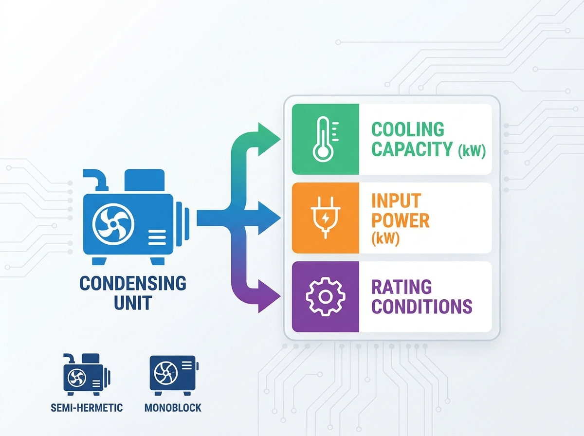
Accurately evaluating refrigeration condensing units requires a strict, analytical framework. You must decode Cooling kW and analyze Input Power under real-world loads. Mastering industry terminology prevents costly procurement errors. Translating standardized rating conditions into application-specific metrics ensures your selected equipment will maintain target temperatures without catastrophic failure or excessive power consumption.
Nominal vs. Actual Capacity: Stated Cooling kW is only valid at the exact rating conditions specified; deviations in ambient or evaporating temperatures drastically alter actual performance.
Efficiency Metrics Matter: Input Power must be evaluated alongside Cooling kW to determine the Coefficient of Performance (COP) and project long-term operational costs.
Technology Impacts Performance Curves: Different architectures, such as semi-hermetic reciprocating compressor units and monoblock refrigeration units, exhibit distinct capacity drop-offs under extreme conditions.
Standardization is Critical: Always verify the testing standard (e.g., EN 13215, ASHRAE) used on the spec sheet to ensure an apples-to-apples comparison between competing units.
Establishing a baseline understanding of key terms prevents procurement miscommunications. The air conditioning, heating, and refrigeration trades share vocabulary, but specific metrics carry different weights depending on the application. A precise grasp of these terms ensures all stakeholders evaluate equipment performance accurately from the design phase through final commissioning.
Commercial refrigeration demands stricter temperature tolerances than standard comfort cooling. Air conditioning focuses on sensible and latent heat removal for human comfort, usually operating with evaporating temperatures above freezing. Refrigeration focuses on preserving perishable goods or maintaining industrial processes, often requiring evaporating temperatures well below zero. Terms like "tonnage" blur the lines between these disciplines. You must rely on precise thermal output metrics rather than generalized HVAC categories when specifying equipment for cold rooms, blast freezers, or process chillers. A five-ton air conditioner and a five-ton freezer condensing unit have entirely different mechanical displacements and motor sizes.
British Thermal Units per hour (BTU/h) and Kilowatts (kW) both measure the rate of heat transfer. Commercial refrigeration spec sheets predominantly utilize kW for thermal output due to its direct correlation with electrical input power calculations. One kilowatt equals 3,412 BTU/h. Using Cooling kW simplifies the process of calculating the Coefficient of Performance. It provides a straightforward metric for engineers sizing both the thermal load and the electrical infrastructure. When a spec sheet lists a capacity of 15 kW, it means the system can remove 15 kilowatts of heat energy from the space every hour under the stated conditions.
Operational pressures directly dictate system capacity. Head pressure refers to the discharge side of the compressor. It correlates directly to the condensing temperature. High ambient heat drives up head pressure, forcing the compressor to work harder to push refrigerant gas into the condenser coil. Suction pressure refers to the inlet side of the compressor. It correlates to the evaporating temperature inside the cold room. Analyzing capacity tables requires translating these physical gauge pressures into their corresponding saturation temperatures using a Pressure-Temperature (P-T) chart to predict actual thermal performance.
Saturated Suction Temperature serves as the baseline metric for evaporator performance. SST is the temperature at which the refrigerant boils inside the evaporator coil. It must always be lower than the target cold room temperature to facilitate heat transfer. A standard medium-temperature room might require an SST of -10°C to maintain a room temperature of 2°C. Capacity tables use SST as the primary variable for determining Cooling kW. If you miscalculate the required SST, you will select a compressor that cannot move enough refrigerant mass to satisfy the room's thermal load.
Understanding how capacity is measured and reported separates successful installations from chronic failures. You must look past marketing labels and analyze the underlying physics of the refrigeration cycle to ensure the equipment matches the physical demands of the facility.
Cooling kW represents the actual, measurable rate of heat extraction under specific conditions. Nominal tonnage is a generalized marketing metric. A "five-ton" unit rarely delivers exactly 17.5 kW of cooling in a real-world application. Nominal ratings assume a fixed set of laboratory conditions that likely do not match your site.
Heat extraction capacity depends entirely on refrigerant mass flow and volumetric efficiency. As suction pressure drops, refrigerant vapor expands. The compressor moves less mass per stroke. This physical reality means a unit rated for 20 kW at medium temperatures might only deliver 8 kW at low temperatures. Relying on nominal tonnage ignores this steep performance curve. You must plot the compressor's capacity curve against your specific operating envelope to find the true Cooling kW.
Thermal output and electrical consumption are distinct metrics. Cooling kW measures the heat removed from the space. Input Power kW measures the electricity consumed to perform that work. Total input power includes several components that must be accounted for during electrical design.
Compressor motor consumption under full and partial loads.
Condenser fan motor draw, which may vary if fan speed controllers are utilized.
System controls, crankcase heaters, and oil management systems.
Defrost heaters, if powered directly from the condensing unit panel.
Electrical infrastructure planning requires analyzing Maximum Continuous Current (MCC) and Locked Rotor Amps (LRA). MCC dictates the sizing of wire gauges, contactors, and standard breakers. LRA represents the massive current spike required to start the compressor motor from a dead stop. Failing to account for LRA results in tripped breakers, pitted contactors, and potential voltage drops across the facility's electrical grid.
The Coefficient of Performance measures the direct efficiency of the refrigeration cycle. You calculate COP by dividing the Cooling kW by the Input Power kW. A higher COP indicates a more efficient system. If a unit delivers 15 kW of cooling while consuming 5 kW of electricity, the COP is 3.0. This means for every kilowatt of electricity purchased, you receive three kilowatts of cooling effect.
COP is not static. It fluctuates constantly based on thermal load, ambient heat, and environmental conditions. High ambient temperatures decrease Cooling kW and increase Input Power, crushing the COP. The industry is shifting toward the Seasonal Energy Performance Ratio (SEPR). SEPR accounts for annualized temperature variations, providing a more accurate representation of long-term energy consumption than a single-point COP measurement taken at peak summer conditions.
Metric | Definition | Application Relevance |
|---|---|---|
Nominal Tonnage | Generalized marketing label based on 12,000 BTU/h per ton. | Poor indicator of actual performance; useful only for basic categorization. |
Cooling kW | Actual rate of heat extraction at specific SST and ambient conditions. | Primary metric for matching equipment to calculated heat loads. |
Input Power kW | Total electrical energy consumed by the unit during operation. | Used for sizing electrical panels and calculating operational costs. |
COP | Ratio of Cooling kW to Input Power kW. | Determines instantaneous energy efficiency at a specific rating point. |
Manufacturer spec sheets present data based on controlled laboratory conditions. You must translate these standardized numbers into the reality of your specific installation environment. Ignoring the rating conditions leads directly to undersized equipment and compromised facility operations.
The target temperature of the cold room dictates the required SST. To maintain a room at -20°C, the refrigerant must boil at a lower temperature, typically around -28°C to -30°C. This temperature differential drives the heat transfer process across the evaporator coil fins.
Cooling kW and COP decline steeply as evaporating temperatures drop. At lower pressures, refrigerant vapor becomes less dense. The compressor cylinders fill with less actual refrigerant mass per stroke. A compressor that easily handles a medium-temperature application will struggle to provide sufficient capacity in a low-temperature blast freezer scenario. You must read the capacity table at the exact SST your application demands, factoring in the specific temperature difference (TD) of your selected evaporator.
Local climate severely impacts condenser performance. The condenser must reject heat absorbed from the cold room, plus the heat of compression generated by the motor, into the surrounding air. If the ambient air is hot, heat rejection becomes difficult, and the entire thermodynamic cycle suffers.
High ambient temperatures increase condensing pressure. The compressor must push against a higher head pressure. This physical resistance increases Input Power. Simultaneously, higher condensing temperatures reduce the refrigeration effect of the liquid refrigerant entering the evaporator, decreasing overall Cooling kW. Sizing a unit based on a 32°C ambient rating will result in failure if your site regularly experiences 40°C summer peaks. Always select equipment based on the historical peak ambient temperature of the installation site.
Capacity tables rely on standard assumptions for useful superheat and liquid subcooling. Superheat ensures only vapor enters the compressor, protecting the valves and pistons from liquid slugging. Subcooling ensures a solid column of liquid reaches the expansion valve, maximizing evaporator efficiency and preventing flash gas in the liquid line.
Lab conditions assume perfect piping and minimal heat gain. Real-world piping distances and degraded insulation alter these variables. Long pipe runs increase suction line pressure drop, artificially raising the SST at the compressor compared to the evaporator. This reduces actual capacity below the published spec sheet numbers. You must apply correction factors for extensive piping networks, vertical lifts, and ambient heat gain along the suction line.
European and North American testing standards utilize different baselines. Comparing a unit rated under EN 13215 directly to one rated under ASHRAE standards guarantees an unequal comparison and skews your procurement data.
Standard | Return Gas Temperature | Typical Application Focus |
|---|---|---|
EN 13215 | Fixed at 20°C regardless of evaporating temperature. | European markets; provides a conservative estimate of useful superheat and motor cooling. |
ASHRAE | Varies based on application (e.g., 18.3°C for medium temp). | North American markets; often aligns closer to specific equipment categories and field conditions. |
Always verify the testing standard printed on the spec sheet. If evaluating competing bids, force the manufacturers to provide performance run sheets normalized to the exact same ambient and SST conditions. Do not accept generic catalog pages as proof of performance.
The internal architecture of the unit dictates how it responds to varying loads and extreme conditions. Selecting the right technology requires matching the compressor's mechanical characteristics to the facility's operational profile and maintenance capabilities.
Heavy-duty industrial applications demand robust mechanical designs. Semi-hermetic reciprocating compressor units offer distinct capacity control advantages. These compressors feature accessible heads, stators, and valve plates, allowing for field rebuilds and maintenance without replacing the entire unit or cutting into the refrigerant piping.
Their primary advantage lies in cylinder unloading. By deactivating specific cylinders mechanically—usually by blocking suction gas to a specific bank of pistons—the compressor can step down its capacity to match partial loads. This prevents short-cycling when the cold room is at temperature but requires minimal cooling to maintain the setpoint. Their performance curves show excellent efficiency retention at partial loads, making them ideal for fluctuating industrial demands like food processing facilities or large distribution centers.
Packaged systems simplify installation and capacity calculations. Monoblock refrigeration units combine the compressor, condenser, and evaporator into a single, factory-matched chassis. Because the manufacturer pairs the components perfectly, the stated Cooling kW is highly accurate for the complete thermodynamic system. Installers simply cut a hole in the insulated panel, mount the unit, and connect the power supply.
However, monoblocks have limitations. They lack the capacity scaling required for massive warehouse applications. Furthermore, because the condenser section often protrudes directly through the cold room wall into the surrounding building space, ambient temperature resilience becomes a critical factor. If the warehouse surrounding the cold room lacks ventilation, the monoblock will suffer from localized high ambient conditions. The heat rejected by the unit gets trapped in the building, driving up the local ambient temperature and drastically reducing the unit's Cooling kW.
Scroll compressors and reciprocating compressors exhibit different volumetric efficiency curves across temperature ranges. Scroll compressors utilize two interlocking spirals to compress refrigerant continuously. They lack suction and discharge valves, which eliminates volumetric losses associated with valve clearance volumes and mechanical re-expansion of gas.
Scrolls typically yield better Cooling kW per Input Power kW in medium-temperature applications, such as walk-in coolers operating at 2°C. However, at deep low temperatures, reciprocating compressors often maintain better capacity curves. Reciprocating designs handle the high compression ratios of low-temperature freezing applications more effectively without excessive discharge temperatures. Understanding these mechanical differences allows you to specify the technology that maximizes efficiency for your specific target SST.
Selecting the correct unit requires translating facility data into a rigorous heat load calculation. Guesswork leads to equipment failure. You must build a comprehensive profile of the thermal demands placed on the system before looking at equipment catalogs.
A comprehensive heat load calculation accounts for every source of thermal energy entering the refrigerated space. You cannot size equipment based on floor square footage alone. You must calculate the exact kilowatt requirement based on four primary load categories.
Transmission Load: Heat bleeding through the walls, floor, and ceiling. This depends on insulation thickness, panel R-value, and the temperature differential between the inside and outside air.
Product Load: The massive thermal energy required to cool down goods brought into the room. A blast freezer pulling meat from 5°C to -18°C requires exponentially more Cooling kW than a holding freezer maintaining already-frozen goods. You must calculate specific heat above freezing, latent heat of freezing, and specific heat below freezing.
Internal Load: Heat generated by forklift motors, evaporator fan motors, lighting, and personnel working inside the space.
Infiltration Load: Warm, moist air entering through doors during loading and unloading operations. This adds both sensible heat and latent heat (moisture) to the room.
Once you calculate the true heat load, you must apply a safety factor, typically 10-15%. This buffer accounts for insulation degradation over time and unexpected operational spikes. However, applying a safety factor larger than 15% pushes you into the dangerous territory of gross oversizing.
Standard capacity tables assume sea-level installation. Installations at high altitudes suffer from lower air density. Less dense air carries away less heat from the condenser coils. You must apply a derating factor to the unit's heat rejection capacity if installing in mountainous regions, which often requires selecting a unit with an oversized condenser coil.
Defrost cycles fundamentally alter capacity requirements. Low-temperature applications require mandatory defrost periods to clear ice from the evaporator coils. During defrost, the system provides zero cooling. If a system requires four hours of defrost per day, it must remove the entire 24-hour heat load in only 20 hours of effective runtime. This requires a significantly higher baseline Cooling kW to compensate for the lost operational hours. Furthermore, electric defrost adds heat directly into the room, which the compressor must then remove once the cooling cycle restarts.
Refrigeration loads are rarely static. A facility might experience peak loads during afternoon loading operations and minimal loads overnight. Variable Frequency Drives (VFDs) and digital capacity modulation solve this discrepancy by adapting the compressor's output to the real-time load.
Variable speed technology alters the frequency of the electrical power supplied to the compressor motor, slowing it down or speeding it up to match the exact thermal demand. This aligns Input Power directly with fluctuating Cooling kW demands. Optimizing the COP during part-load conditions drastically reduces annualized energy consumption. VFDs also eliminate the massive starting current spikes associated with fixed-speed compressors, reducing mechanical stress on the motor windings.
Failing to match unit capacity to site realities triggers a cascade of mechanical and financial failures. Both oversizing and undersizing carry severe consequences that impact the facility's bottom line.
Many engineers oversize equipment out of an abundance of caution. This is a critical mechanical error. An oversized compressor pulls down the room temperature too quickly and shuts off. This rapid cycling is known as short-cycling.
Short-cycling destroys equipment. Compressors rely on sufficient run times to circulate oil through the piping network and return it to the crankcase. Short-cycling traps oil in the evaporator, leading to premature compressor wear and eventual mechanical seizure due to lack of lubrication. Operationally, short-cycling prevents the evaporator from running long enough to remove moisture from the air. This causes poor humidity control, severe frost build-up on products, and compromised indoor air quality within the walk-in.
Undersized equipment fails to maintain setpoints during peak loads. The financial impact is immediate. Product loss due to temperature excursions destroys profit margins. In pharmaceutical or food processing applications, failing to maintain strict temperature logs results in regulatory non-compliance and forced product destruction.
Mechanically, an undersized compressor runs continuously. It never satisfies the thermostat. Continuous operation leads to severe overheating, oil breakdown, and catastrophic motor burnout. The discharge temperatures climb beyond safe limits, carbonizing the compressor oil and destroying the internal valves. The cost of replacing a burned-out compressor far exceeds the initial savings of purchasing a smaller unit.
Mechanical capacity means nothing if the facility cannot power the unit safely. You must align the unit's electrical requirements with existing infrastructure before finalizing the purchase order.
Verify the facility's incoming voltage matches the unit's requirements exactly (e.g., 400V/3Ph/50Hz). Voltage imbalances destroy three-phase motors rapidly.
Confirm the main electrical panels and transformers can handle the unit's Maximum Continuous Current alongside existing facility loads.
Evaluate the Locked Rotor Amps. Large commercial units require massive starting currents that can dim facility lights or trip main breakers.
Install phase monitors to protect the compressor from phase loss, phase reversal, or voltage asymmetry.
Mitigate electrical risks by installing soft starters or VFDs. Soft starters ramp up the voltage gradually, eliminating the violent current spike associated with direct-on-line starting. This protects both the compressor mechanics and the facility's electrical grid.
Demand custom performance run sheets from manufacturers based on your specific peak ambient and target evaporating temperatures.
Calculate your facility's true heat load, factoring in transmission, product, internal, and infiltration variables, before looking at equipment catalogs.
Adjust your required Cooling kW to account for lost runtime due to mandatory daily defrost cycles.
Verify your electrical panels and transformers can handle the unit's Maximum Continuous Current and Locked Rotor Amps.
Engage a qualified refrigeration engineer to validate all heat load calculations and piping designs before finalizing equipment selection.
A: Nominal capacity is a generalized marketing term, often expressed in tonnage, based on standardized lab conditions. Actual Cooling kW is the precise rate of heat extraction the unit delivers at your specific site's ambient and evaporating temperatures. Always size equipment based on actual Cooling kW.
A: You must perform a comprehensive heat load calculation. This involves quantifying transmission heat through walls, the thermal mass of the product being cooled, internal heat from lights and motors, and infiltration from door openings. Finally, adjust this total to account for lost runtime during mandatory defrost cycles.
A: High ambient temperatures make it difficult for the condenser to reject heat. This drives up the head pressure. The compressor must work harder to push refrigerant against this elevated pressure, which directly increases the electrical Input Power required to keep the motor running.
A: Manufacturers test equipment according to regional standards, such as EN 13215 in Europe or ASHRAE in North America. These standards utilize different baseline assumptions for ambient temperatures, return gas temperatures, and useful superheat, reflecting different regional climates and engineering practices.
A: Yes. Monoblocks are rated as a complete, factory-matched thermodynamic system. The stated capacity reflects the exact pairing of the internal compressor, condenser, and evaporator. Split systems require engineers to calculate the capacity based on how a specific condensing unit pairs with a separately selected evaporator coil.
A: You calculate the Coefficient of Performance (COP) by dividing the unit's Cooling kW (thermal output) by its Input Power kW (electrical consumption) at a specific rating condition. For example, 10 kW of cooling divided by 4 kW of input power yields a COP of 2.5.
A: As evaporating temperature drops, suction pressure decreases. The refrigerant vapor expands and becomes less dense. The compressor moves less actual mass of refrigerant per stroke. This loss of volumetric efficiency results in a steep drop in the unit's overall Cooling kW capacity.